


News
Mill Creek Tunnel Project Spotlight
Mill Creek Tunnel Project Spotlight https://www.southlandholdings.com/wp-content/themes/corpus/images/empty/thumbnail.jpg 150 150 Southland Holdings https://www.southlandholdings.com/wp-content/themes/corpus/images/empty/thumbnail.jpg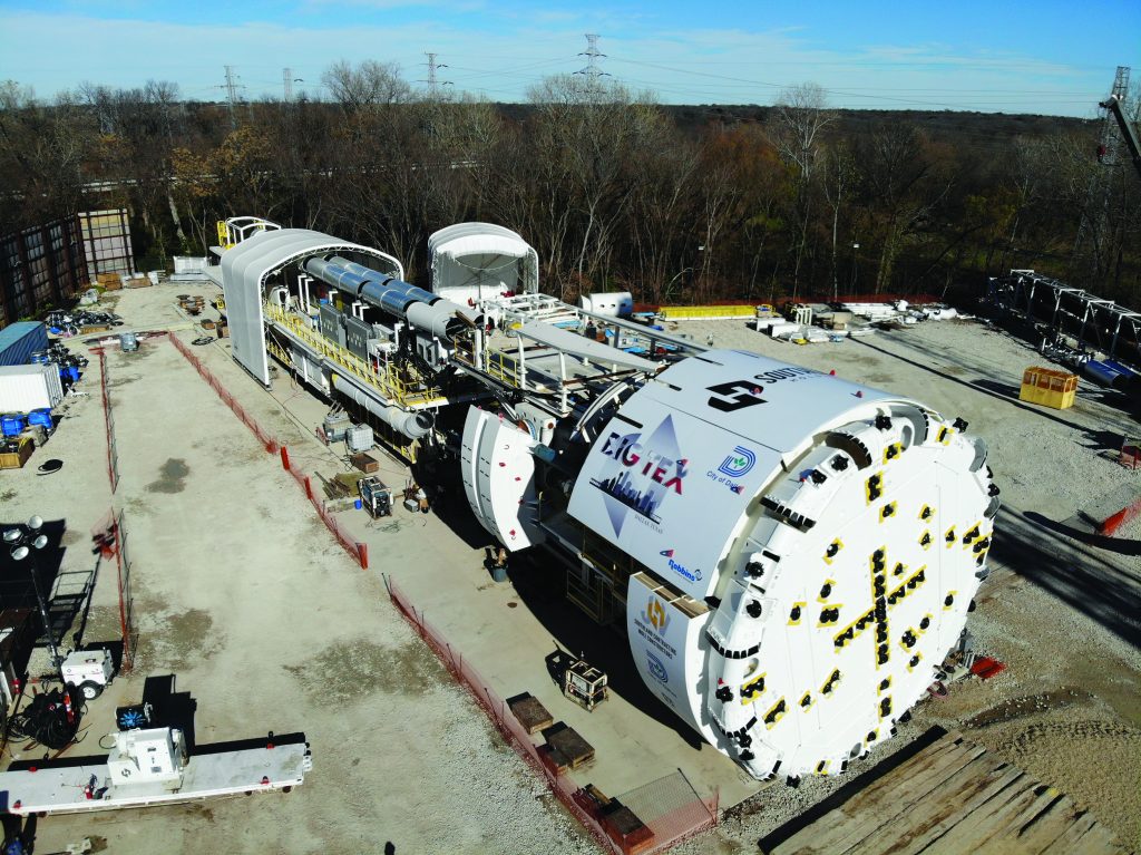
Mill Creek Tunnel, being built by the Southland/Mole joint venture for the City of Dallas, has moved into concrete lining operations after one of the largest hard rock tunnel boring machines (TBMs) ever used in the United States completed mining in July 2022. “Big Tex,” as the TBM was nicknamed, began mining with a 37.5 ft diameter before converting to a 32.5 ft diameter about 2 miles into the 5-mile-long excavation.
The project has received recognition from all corners of the engineering and construction community, including earning a “TECHNICAL INNOVATION OF THE YEAR” award from the International Tunneling Association (ITA), for Unprecedented In-Tunnel Diameter Conversion, of the Largest Hard Rock TBM in the U.S.
Drainage issues surrounding the Mill Creek Tunnel were originally identified in 1970. Major flooding events through the 1990s and 2000s, including a major storm in May 1995 that flooded the Baylor Hospital emergency room and closed Interstate 30, reinforced these needs.
The 5-mile-long, 37.5 to 32.5 feet in diameter tunnel, has five large intake structures along its route to intercept existing storm sewers. These intake structures will prevent flooding along the tunnel alignment, and the tributary storm sewers that will connect to the tunnel. Once flow is collected, the tunnel will direct flow east to an outfall structure along White Rock Creek, where it will be released, avoiding flood damages in east urban Dallas.
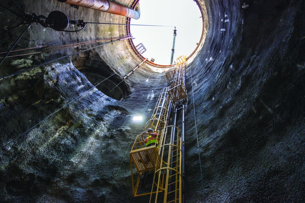
Once complete, the tunnel will function hydraulically by gravity as an inverted siphon. Since the elevation of the outlet structure is lower than the intake structures, water that enters the tunnel will fall down the 100 to 150-foot-deep intake shafts, and be carried through the tunnel. It will then rise out of the 100-foot-deep outlet structure entirely by gravity. Although the Mill Creek Tunnel is larger than its predecessors, it will function similarly to the San Antonio River Tunnel built by the USACE in San Antonio in the late 1990s, and the Waller Creek Stormwater Tunnel built by the City of Austin in the 2010s. Both projects have been credited with significant flood damage reduction.
The Mill Creek Tunnel is now an example for future stormwater tunnels, including efforts in Houston to mitigate flooding after Hurricane Harvey.
Like many large, complex projects, the Mill Creek Tunnel required innovation by the construction team due to the sheer scale of the project. The TBM provided by Robbins, nearly a football field in length, was fully assembled on-site for the first time, with parts being sourced globally to Southland/Mole’s main work site in east Dallas. This method expedited TBM delivery, assembling, mining start, and significantly reduced the cost to mobilize such a large piece of equipment. The TBM was fully assembled at the surface, then lowered in sections, into the tunnel with a specialized heavyweight crane.
The in-tunnel diameter change was an industry first, and required portions of the cutterhead to be removed from the machine and transported through an adit connection. All of this was done without a disassembling chamber.
Because of the expansive tunnel diameter, the TBM produced a colossal amount of muck that was conveyed from the machine to the surface. At 37.5 feet excavated diameter, each foot of excavated tunnel produced over 60CY of spoils to handle on the surface (Including fluff-factor for the soft rock. The tunnel muck required 200 trucks per day), and had days reaching 500 truckloads when production was at capacity. The mining operation averaged approximately 50 LF/day once all downtime was considered. The best day of production achieved 170 LF with the best week of production reaching approximately 600 LF.
Since this is a two-pass tunnel where the mining and the tunnel lining are completed in separate activities, the focus of the tunnel has now shifted to concrete lining operations, which are expected to be completed in 2025. The concrete lining, which consists of 15-inch-thick unreinforced concrete, will require 130,000 cubic yards for the 5-mile length of the tunnel, or 14,400 concrete truck loads. Placement of the concrete requires careful coordination by the construction team to ensure concrete quality meets the project specifications. Large agitating hoppers are used to move the concrete miles into the tunnel from the shaft to the placement location. These hoppers can each hold 13 CY weighing approximately 60,000 lbs when fully loaded. Once the hoppers reach the placement location, concrete is pumped into a large custom tunnel formwork system, which places the concrete in lengths up to 100 LF (500 CY).
Stay tuned for more project updates as concrete lining wraps up and the project goes fully online in 2025.
Project Stats
- CONTRACT VALUE: $212,000,000
- NTP: March 2018
- ESTIMATED COMPLETION: December 2025
- EXCAVATED MATERIAL: 100-150 individuals depending on current activities.
- 1,500,000 CY from Main Tunnel alone. Total job would reach approximately 2,000,000 CY of material excavated.
- CONCRETE: 130,000 CY of concrete placed in Main Tunnel alone. Total job would reach approximately 170,000 CY of concrete.
- 5 total miles of tunnel through Austin Chalk Formation (Limestone).
- 2 miles at 37′-7″ excavation with 35′-0″ finished concrete liner.
- 3 miles at 32′-7″ excavation with 30′-0″ finished concrete liner.
- Excavated by method of TBM.
- Support consisted of wire mesh, 14″ long rock bolts, and steel channel as necessary.
- 8 total shafts ranging from 100VF to 180VF in depth, and ranging from 14′ diameter to 45′ diameter – includes 1 outfall shaft, 5 drop shafts, and 1 dewatering shaft. All consisted of liner plate/ring beams through the overburden, and rock bolts, wire mesh, and shotcrete through the rock. Excavated conventionally with excavators and hammers/breakers. All to be finished with Cast in Place (CIP) concrete liner.
- 6 total lateral tunnels connecting to the Main tunnel, ranging from 50 LF to 500 LF in length, and ranging from 12′ to 25′ diameter (horseshoe shaped excavations). All initial support consisted of wire mesh and rock bolts. Excavated conventionally with roadheader or excavators with hammer/breaker (Horeshoe shaped excavation). All to be finished with CIP Concrete Liner (circular finish).
Structures
- 4 large intake structures designed to intersect with the drop shafts to create a vortex.
- 4 large junction Boxes constructed on live storm systems.
- Mega-inlet structures.
- CIP Inlet structures.
Surface Improvements
- 4000 LF of storm system improvements (Concrete Box Culverts – 9×9, 10×10, 12×12, Concrete pip, storm inlets, etc).
- 5000 LF of water line improvements.
- 5000 LF of sanitary sewer improvements.
- Concrete and Asphalt Paving.
- Sidewalks, curb and gutter, walking trail improvements.
- Traffic Signals, residential street lights, signage.